As I announced here before, I am currently working on a DIY controller for GP. It will have the following properties:
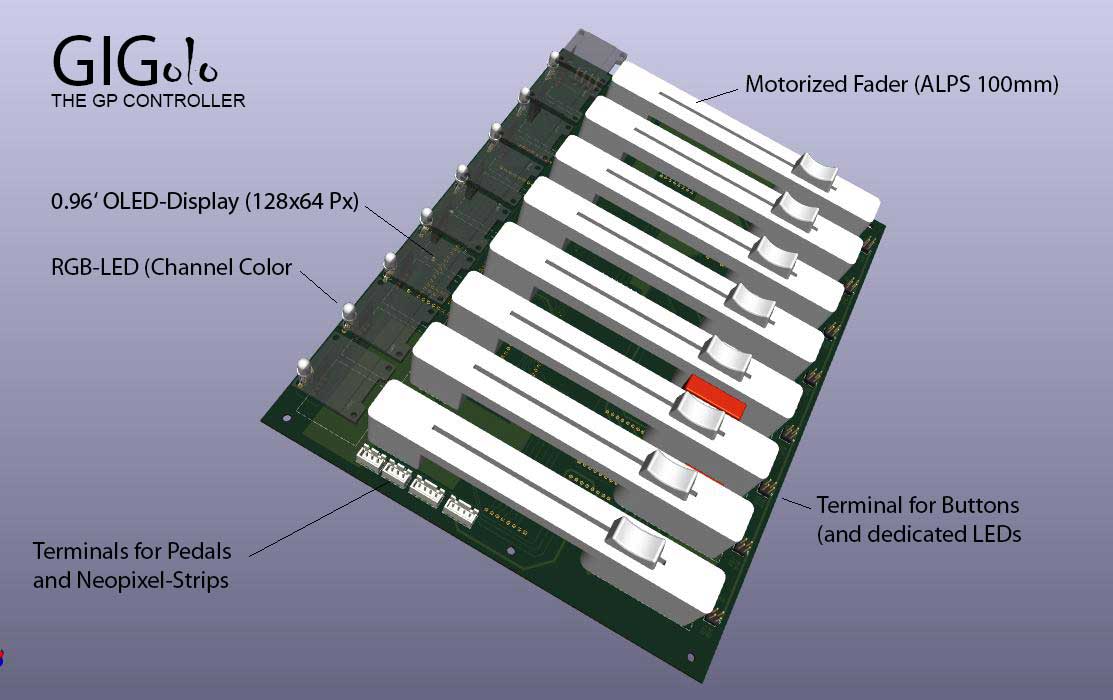
8 channel strips, each with a 0.96’ OLED display (to display the assigned sound or function) and a button (to trigger a sound or midi file, for example).
The channel strips also feature an RGB LED so that the assigned channels can be “color coded”. The color-coding can be transferred to Neopixel LED strips that are mounted on the keyboards and mark the corresponding keyboard split areas. These LED strips are controlled directly via the controller.
Furthermore, the controller - which I will call GIGolo by the way - has 6 buttons that can be used, for example, to step
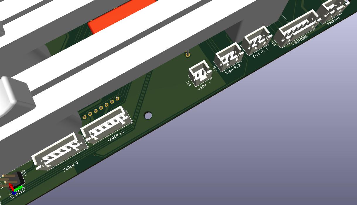
through songs or song parts. Finally, there are two analog inputs for expression pedals or similar, as well as 2 pedal inputs.
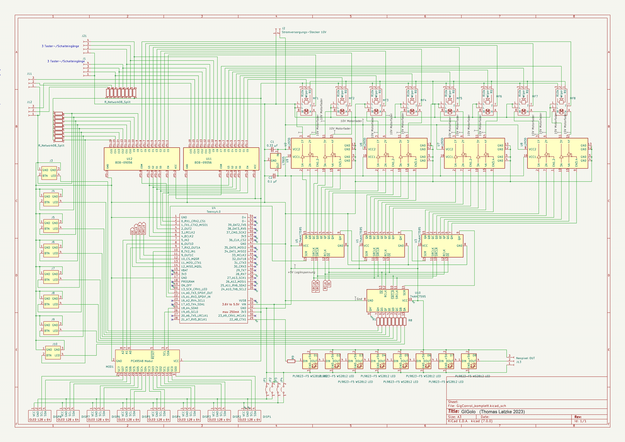
The circuit diagram is ready and the board layout is also in place.
I assume that I will have the GIGolo ready to use by the summer.
Which faders specifically are you looking at incorporating? I assume from your description it’ll be one of these guys?
Color or mono OLEDs? I’m guessing mono based on the RGB LED right above it.
Any thoughts on communication protocol (which I assume will be midi-based)? Given the design I would think a Mackie MCU type protocol makes sense?
This takes me back to my electrical engineering days, where my undergrad thesis project was to build a “low cost programmable 8x8 MIDI merger/router.” That was 32 years ago now. Hard to believe we’re all still using MIDI!
Yes you’r right: the faders are ALPS RSA0N11M9A0J which I bought here on Aliexpress.and the OLEDs are monochrome displays.
The communication-protocol will be based on Midi-messages adapted to GP (display content = MIDI sysex messages, faders and buttons = MIDI Control Change Messages). communication takes place via USB.
I will publish the program code for GIGolo (written with the Arduino IDE for Teensy) and for my purposes written GPscript here in this place - hoping, the community will help to optimize it
I will definitely do that. As soon as I have verified the circuit board layout using a sample production, I will make it available here together with the parts list etc.
What do you think of a 9+1 fader layout?
This would be great for a “drawbar plus main volume” control… every controller on the market “only” has 8 faders, yours could stand Out if it had 10.
In view of the fact that you often get the faders in packs of five, I actually thought about such a constellation. But I wanted to keep the board as compact as possible and therefore limited myself to the 8-channel solution. After all, additional faders (and displays) require additional ICs for control and correspondingly more space… But maybe I should think again. I’ve also considered integrating an expansion port, which can then be used to connect another 4 or 8-channel module…
Yes, I actually had my eye on using GIGolo as a drawbar module. In particular, because nowadays it is relatively easy to implement a corresponding mechanism for the motor faders with the 3D printer.
This looks like an excellent project. I’ve been using the Teensy boards for MIDI controller projects too, it’s an incredibly capable microcontroller board.
I wasn’t aware of the PCA9548 chip to multiplex I2C connections, that’s a very interesting discovery for me as I currently only drive a single OLED with a direct I2C connection. Is there a reason for using this method rather than to target addressing individual slave OLEDs chained directly on the same bus?
The usual OLED displays, which I also use in this project, only have two programmable addresses. Therefore, no more than two displays can simply be connected in parallel if they are to show different information.
I have thought about this suggestion from Schamass and have come to the decision to change the circuit to use 10 faders (by adding one shiftregister SN74HC595 and one motordriver l293d to it).
However, the two additional channels will not have a display. But that is not absolutely necessary for the intended use as a drawbar. The same applies to using one of these additional faders as a master fader.
This is a great idea, and it’s very kind of you to be willing to share the design with others here. Do you have an estimate on what it will cost to build? I see 10 faders are around $110 US which is less than I expected.
The cost of all components should be less than 300 EUR. A lot depends on the price of the board. If there are many interested parties, the production costs could of course be significantly reduced by the larger number of items.
For the sample production of three circuit boards, I reckon with a total price of just under 90 EUR.
Really nice to see projects like this one. Myself, I’m dreaming of building a modern MIDI foot controller to replace my Rocktron All Access - that pedal is over 20 years old and it has a big clunky circuit board inside - who knows when that’ll break down?
The aluminum exterior case is really sturdy, so I’d actually consider replacing the innards with something more modern. Also, it’s only editable on-device: I would love to have something inside it that could be edited from an app or similar.