STJØRN - Custom MIDI controller for Gig Performer based rig

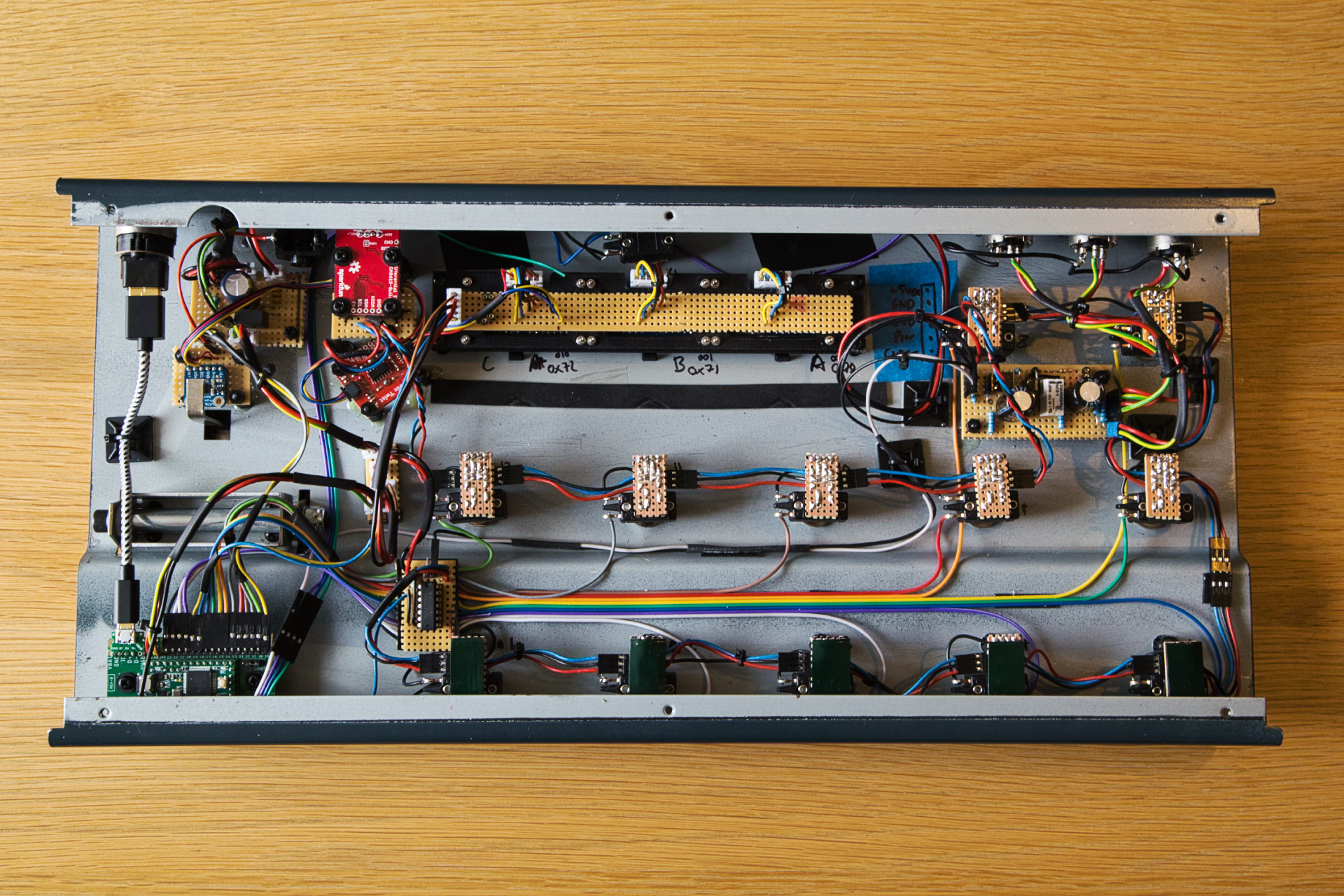
After far too long of being ‘in the process of’ making a custom MIDI controller I have actually started!
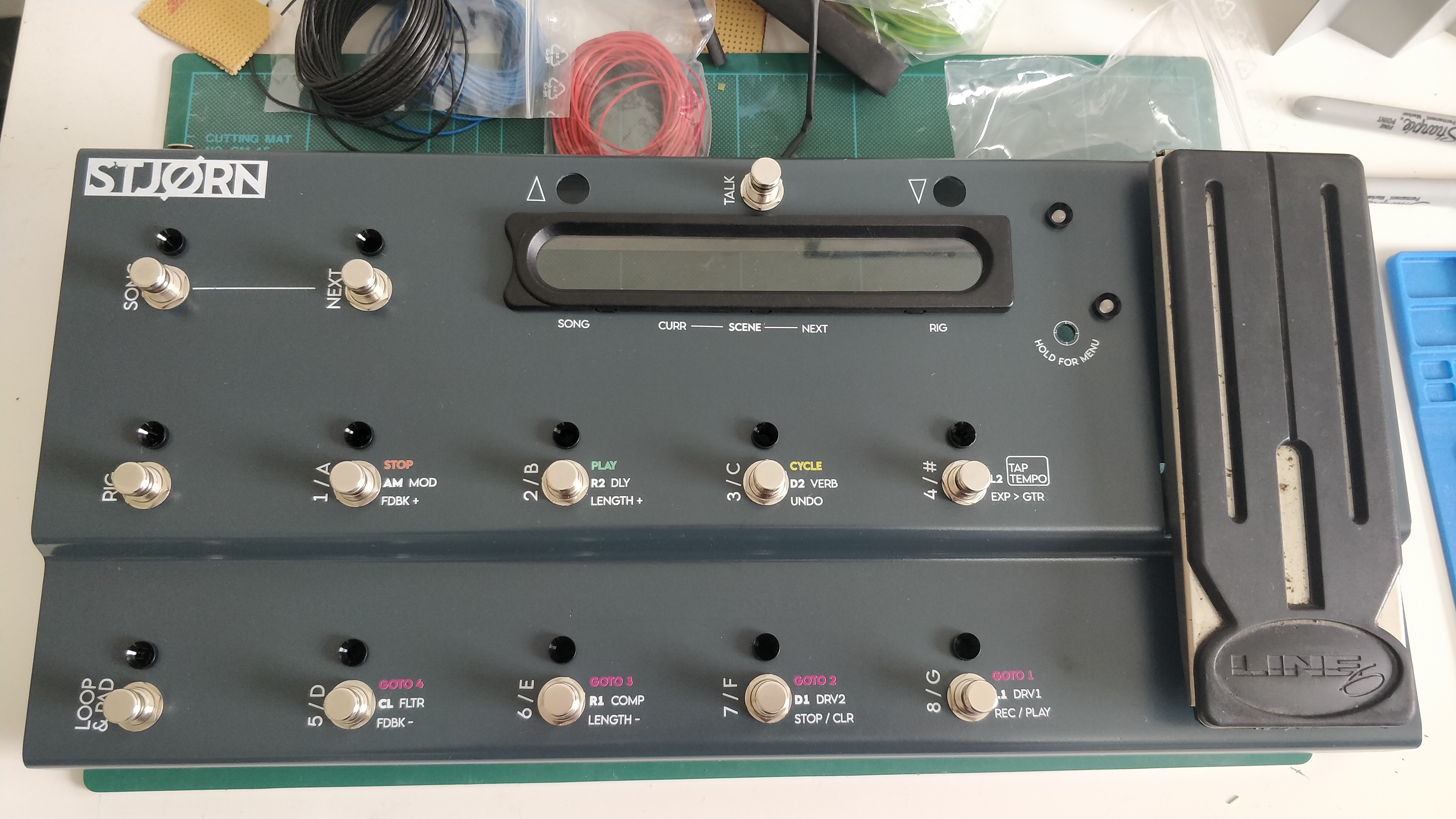
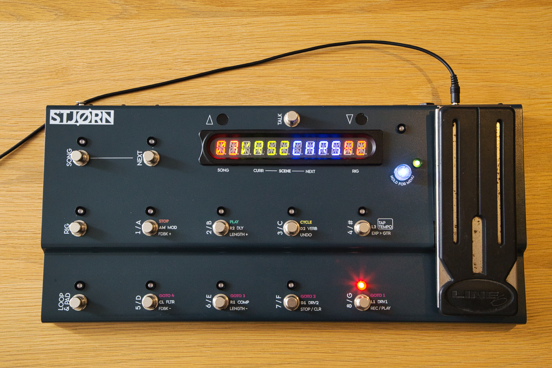
Welcome STJØRN.

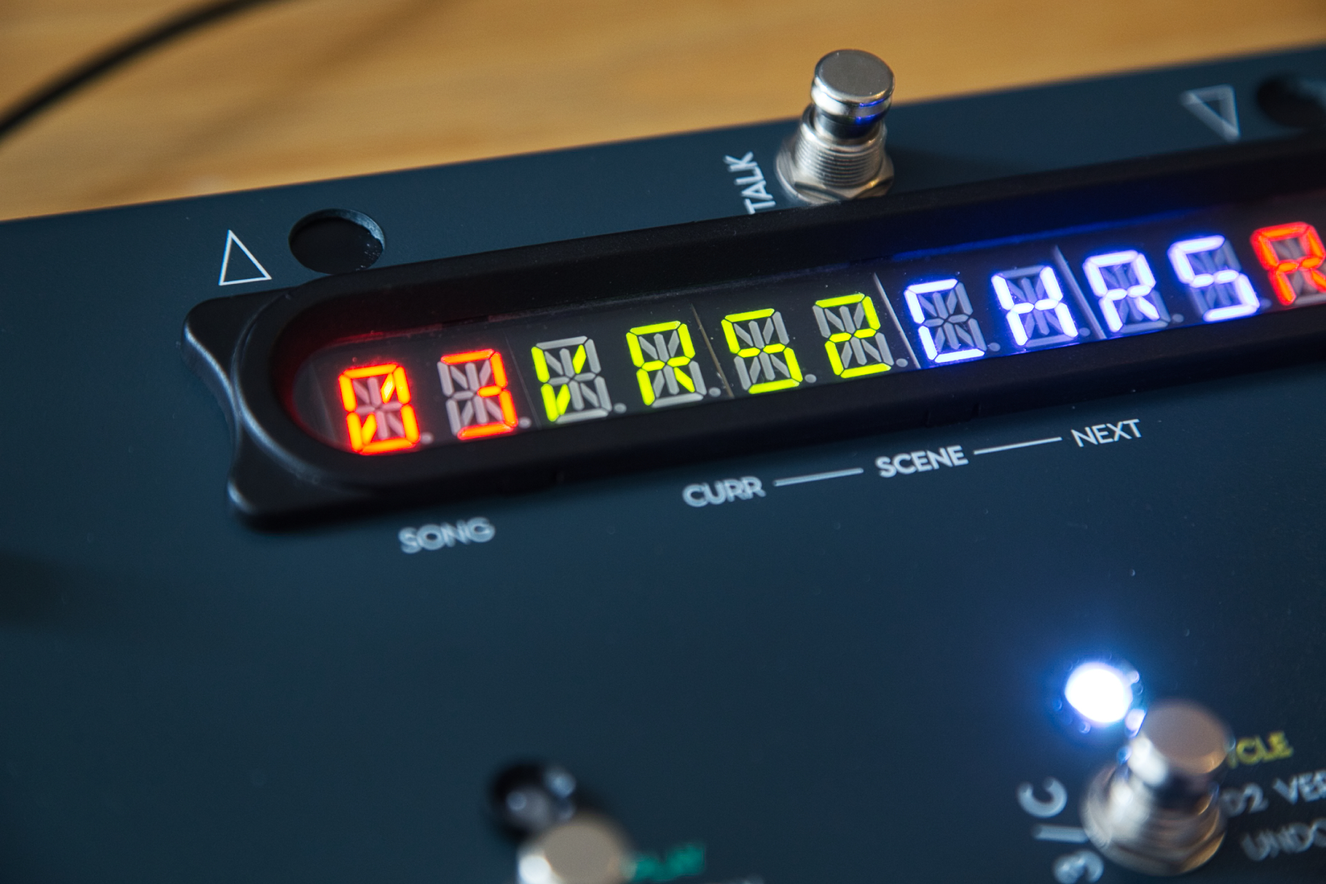
I have long wanted a MIDI controller to control a GP based rig that works how I want it to work. My live use needs both foot control (I’m a guitarist) over GP but also foot control of Ableton Live to control backing tracks and clicks. I also wanted the controller to display info on the tracks as a sort of HUD.

As mentioned, I have been planning this for - literally… - years and although the concept has remained the same the way to apply it has changed somewhat. The ‘final’ form that I have now started to build is actually quite a lot more simple than it started and theoretically could be achieved using an off-the-shelf controller, but still with some compromises over how I want it to work and so I am sticking with this!

I have started a project over on Hackaday.io to document the build - this can be found here:

If you are interested, please follow it and I will try and update pretty regularly. I will probably also post in this thread when there is an update. Hopefully it might inspire some of you in similar situations to have a crack at building your own controllers :slight_smile:. I would also love any feedback and suggestions on any part of it so feel free to fire away!

Splendid.

6 Likes

Best of luck :wink:
Intrigued by the name…
(STJØRN means ‘control’ in Icelandic)

Good luck with the project! I’ve been following one that someone local to me has done. Also well worth checking out.

Best of luck @speed12 . I’m sure this will be a well thought out controller

Ah cool, thanks for sharing - this looks to be using a Teensy microcontroller as well; it’s a great little (literally, it’s tiny!) board for these sort of projects as it has native USB MIDI which makes life very easy for programming!

Thanks - and everyone else as well! - hopefully it will be; looking forward to finally getting it completed!

I ended up buying this, and have already been getting dirty with soldering new connections and doing some re-programming :slight_smile:

I was able to order it with two expression ports, so my tinkering was to convert one to use a dual momentary aux switch (using for up/down in GP). What’s nice about it is the red/green LED rings around each foot switch are bi-directional, so will sync with my widgets when I change variations/rackspaces.

Anyway, learning something new!

1 Like

Ah great!

STJORN is coming along also - need to actually put some project updates up…will get around to that this week!

2 Likes

(Prompted by the above…)

First few project updates for those interested! :slight_smile:

https://hackaday.io/project/162616/logs

1 Like

New update on the microphone switcher circuit that is incorporated in to this controller. Enjoy :slight_smile:

1 Like

New update for those interested - it now has some paint and snazzy graphics!

6 Likes

Long delay, but posting a quick update on this build - the electronics have been complete for around a month now but have only just got around to posting an update!

Really pleased with how it all went together and best thing is that it all works! Only a single minor mod was required to put a capacitor discharge resistor across the main power cap as it was causing some strange problems with the WS2812 LEDs, but once that was in it all works really well.

Programming has started and is progressing slowly - I have it functioning as a very basic MIDI controller but still lots to do to implement all the bi-directional and state machine functions to get it to control GP and Live how I want. But with the UK fast looking like we’ll be in another lockdown soon I might get a good chance to get this done…

Anyways, a few photos of the completed hardware below :slight_smile: Hopefully won’t be as long until the next update…

Lights are on and someone is at home!

Complete gut shot

USB connection and power-board (board with large cap); black rectangle you can just see is the 5V DC-DC for isolated power to the mic switching board

Adafruit proximity sensor board positioned to use the proximity bar from the existing line 6 hardware

The small red board - at an angle to fit around the standoffs for the other boards - is the RGB rotary encoder. The larger red board is the i2C differential board allowing i2C comms over an ethernet cable

The LED screens are mounted using a combination of the original line 6 external bezel, and a 3D printed mount - the black mount wiht screws you can see - to hold the three displays together and allow use of the original mounting hardware

Each footswitch has a small board - attached with self adhesive foam tape - to handle the connections for the WS2812 RGB LEDs as well as the small cap that each needs. In hindsight I should have had some small PCBs made up, but these do the job

This is the mic switch board. It uses a relay to switch between the two XLR mic inputs and output to a common XLR output. The power comes from the 5V DC-DC and there is an opto-coupler between the arduino signal and the relay so that the audio circuit is completely isolated from any of the digital electronics.

And last, but not least, tucked away in the corner is the brains - the Teensy 3.2 micro-controller. It is mounted to a breakout board from TallDog which allowed me to put right angle connectors for all the pins, right angle USB, etc

8 Likes

Amazing :+1:

Beautiful work! Takes my back to my hardware design days in the early '80s. Sure don’t miss wire wrapping!