It worked fine for me with the RME driver. I didn’t test that extensively because I didn’t have a use for it with my RME Babyface. The only thing I’m using it for is to give me multiclient ASIO support for my Focusrite, which lacks mutliclient ASIO support in the driver.
Here’s a quick overview of how it works and how I’m using it. (Note, these images are cut from the manual and not my actual system, because I’m not at home now.)
There are two configuration windows for the program. The first (below) sets up and starts the virtual ASIO device. It looks like this:

That “Channels IN/OUT” line is where you set how many virtual ASIO ins and outs you want. It defaults to 64, which is way more than I need and makes the in and out blocks in GP huge. I reduced mine to 24. This is where you need to make this choice, though.
I check the “Start minimized” and “Start with windows” boxes under Tool settings, and “Start ASIO Link Pro Minimized” and “Do not check for updates”. That sets it so the second configuration window (below) doesn’t automatically pop up on your screen every time you start GP or any other app where you have ASIO Link set up as your ASIO interface.
Then you hit the “Init ASIO” button then the “START ASIO” button. This is analogous to physically plugging in an interface device (e.g., it tells Windows this virtual device called “ASIO Link” is now connected.)
You can close that window, and any time you want to pull it up again you can grab it in the icon tray. It’s the purple keyboard icon.
Once you’re in GP and you select ASIO Link as your virtual interface you’ll get a control panel like below for setting up the routing. This will be available in your icon tray as a green keyboard looking icon.
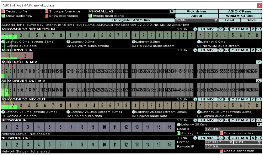
Each of the boxes with a little number in it represents an audio channel (all mono). The top row is for WDM devices, which I don’t use so I leave completely disconnected.
The second row (labeled ASIO DRIVER IN) are the inputs on your device. In this example there are only two. My Focusrite 18i20 shows 18. When you mouse over them it shows you what your interface calls them (e.g., “ADAT 6”, “Analog 1”, “SPDIF in” etc.) on that status line up above.
Those middle two rows are the virtual ASIO ports it creates. This image shows 64 of them. Like I said above, I reduced mine to 24 to make it easier to work with.
The line labeled “ASIOVADPRO MIX OUT” represents virtual WDM devices, which I don’t use so I ignore it.
Those bottom two lines “NETWORK IN” and “NETWORK OUT” are for linking to other instances of ASIO LINK running on other systems on your network. Again, I don’t use these. An alternate use of these is for coupling multiple physical audio interfaces on the same machine together. Like if I wanted to drive my Traveler and Focusrite at the same time out of GP I could do it with this through the network loopback interface (127.0.0.1), but I haven’t messed with this and just ignore it.
First thing I did when setting up this patch panel is hit all the little “X” buttons toward the right above each line of channels. That just erases any existing connections, which I did because I didn’t want any of those virtual WDM devices doing anything unexpected.
Then I went to the ASIO DRIVER IN line and hit the first “1-1” button. That puts in a virtual patch cable from ASIO DRIVER IN 1 (i.e., the first input on your physical audio device) to ASIO HOST IN MIX 1 (the virtual device that shows up in GP or whatever other app). It does that for all the inputs, basically mapping them 1-1, so for my interface it makes 18 lines from my interface’s 18 inputs to the virtual device’s first 18 inputs.
With that done, I hit the “Save” button, give a filename in the dialog that pops up, and that becomes the new “Profile 1” in the dropdown box to the left of it. You can save up to 8 of these configurations for quick access in that Profile dropdown.
Your Audio in and out boxes on GP’s patch panel will now be called ASIO Link (assuming you select that in Audio Setup) and will have the number of inputs and outputs you chose in that first configuration window I showed above. (I made mine 24.)
Hopefully that answers your question regarding “agglomerating the RME and virtual inputs.”
Out of curiosity, why would you use this (or ASIO4ALL) with an RME?