One of the things I have missed from “the program that shall not be mentioned”, is the keyboard split and layer indication. Some of the music I play has some complex splits and layers going on, it would be nice if I could get a reminder of where they are, especially when the songs are recently learnt.

I did like the look of the NI Kontakt Komplete Kontrol as it has LEDs that can indicate the zones, but more keyboards, the wife would leave me. I am happy with the boards I have, for live use and at home, so an idea popped into my head. Off to AliExpress…..
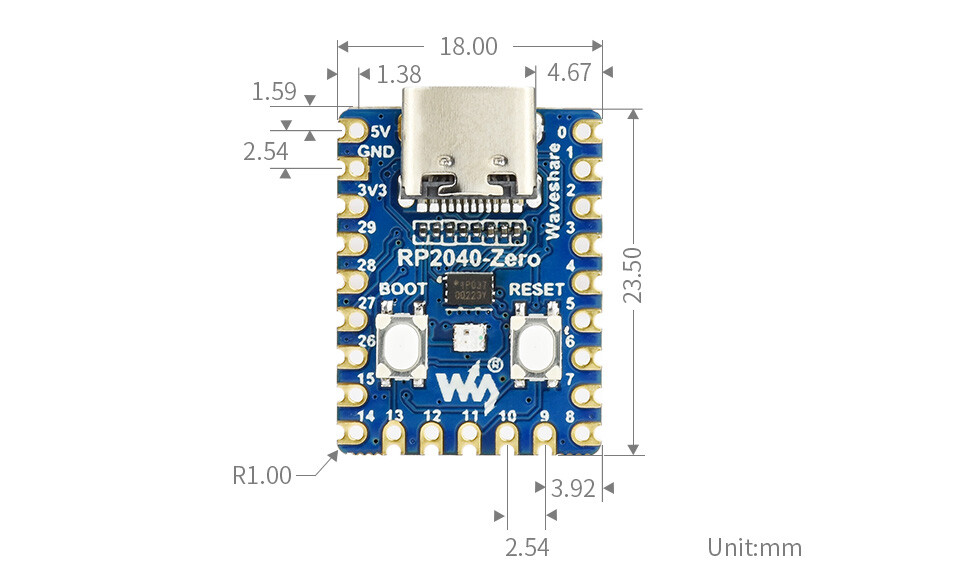
I bought a bundle of 10, RPi Pico boards (small but capable development boards) for 15 quid, then a string of Neopixels, again about 15 quid. The neopixels were 144 pixels per metre, which was pretty close to twice what I needed. When they turned up it was 72 pixels per 0.5m with a joint in the middle. To be fair the blurb did say there was a joint but it does remove the linearity every 500mm.
So the plan is to build a prototype on my ageing Kurzweil K2500, of a LED strip that I can use to see the zones. I am not planning to integrate it into the K2500, but it must fit to any board. Secondly it must work with Gig Performer and not destroy any of my rig functionality if the Led strips are not fitted. At this point I will say that the K2500 and my Korg Triton both have GP patches that simply make them simple controllers, I do not rely on splits/zones or sounds from the keyboards, all zone control is from within GP.
A bit of programming later ……
I now have the first prototype fitted to the K2500 (ignore the spare wires). Using every other LED was almost spot on, but when it came to the join then it ran off the key alignment. I decided to break the join and remake it to get the alignment back, this involved lighting the two adjacent LEDs across the new joint, so the note to LED mapping was now slightly complicated.


After a couple of tries I ended up with the 88 notes covered in three sections of LED’s but the nature of the neopixels is, they all just work as a linear array regardless of where the joints are. The software on the RPi Pico can deal with the complication. Some basic testing looked good so I ploughed on.
On the Korg Triton the keys are fractionally narrower and a slightly different approach was needed to hold the alignment, this time the neopixels were cut into octave lengths (23 pixels) with each odd position used, this limits the runoff and the difference is adjusted at the join every octave, so helping to keep the alignment.

The octave splitting/joining technique will work for any size board and provides a consistent (although not linear) note to LED mapping regardless of size. The LED strips have a fairly low tack self adhesive strip on the back and can easily be removed with no damage. So, I will redo the K2500 at some point, using the same scheme, but for now the RPi Pico can deal with the differences.
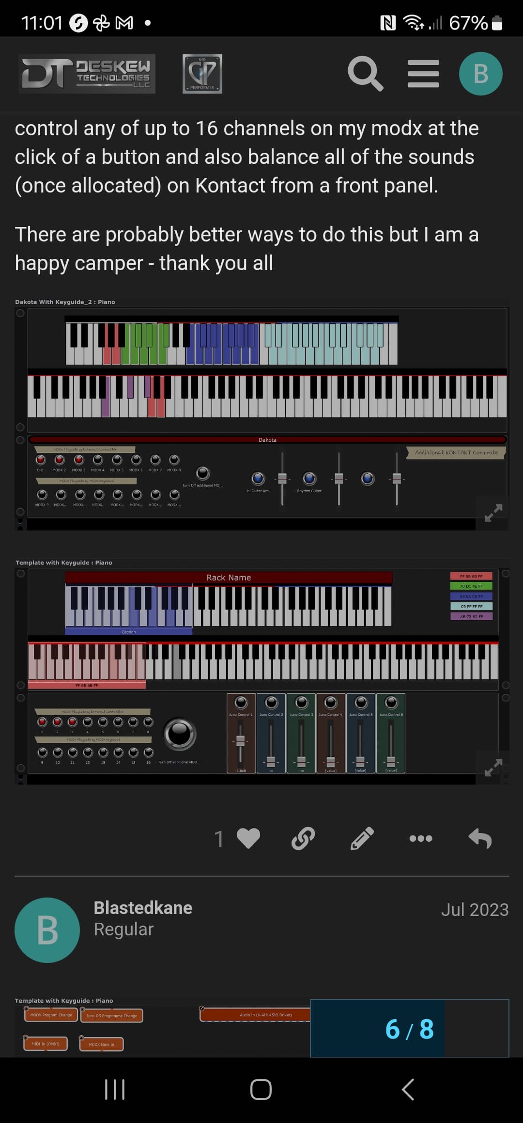
So with both my keyboards retro-fitted with “KeyZone”, it was time to delve into GP and get it working. It turned out to be very simple and does not require any scripting. The following shows the various zones being selected as I move through the song parts. A short video is here,
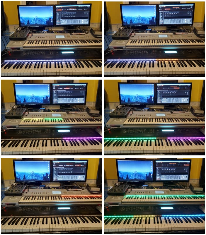
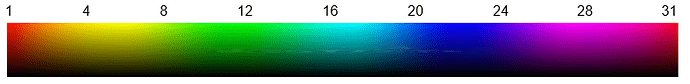
I decided to organise the colours, based on type of sound or source, White Piano, Orange Mellotrons, Yellow Sequencers and Arps, Green Pads, Purple Organs, Red hard leads, Less Red soft leads, and Blue Percussive and Chimes. I was pretty pleased with the results.
Global Rackspace
The RPi Pico is powered by USB and has a USB-MIDI interface that can be seen as a MIDI device within Gig Performer. The first thing was to get note on and note off to go to the Led strips, regardless of patch and zone and very importantly transpose. This would be optional if you didn’t want to see any key press indication.
In the global rackspace I added this straightforward wiring. This simply routes everything from the Rig Manager keyboard alias’s MIDI In to the MIDI Out, one per keyboard.

The settings on the MIDI In blocks are identical for both units. They just filter out everything except note on and note off messages. The “Ignore global transpose” must be selected.

There is one more piece to be completed in the MIDI Out blocks. SysEx messages are added and the “Reset on deactivation” option must be selected. Rechannalising does not matter as the LED strip responds in omni mode. The information in the SysEx message is slightly different in each block depending on the keyboard it is fitted to. This is used to initialise the units when loading a gig file and to turn off the units when closing a gig file.

Local Rackspace
The implementation here was even more straightforward than the global rackspace. Two MIDI out blocks are added, one for each keyboard. No wiring is needed to these blocks.

Each output block is set up with “Reset on deactivation” selected and a SysEx message added. The SysEx message is sent when the rackspace is selected. Each SysEx message is slightly different and is used to define the zones used on that keyboard.

No alterations were made to my existing Rackspace wiring.
Rackspace Variations
In order to turn on and turn off the zones a number of CC messages can be sent to the RPi Pico, this allows various zone combinations to be selected as the rackspace variations are changed. A single widget one per keyboard is added to the panel and mapped to the CC message that enables or disables the zones. Optionally a widget per zone could be added to give a simpler user interface, but it is far more complex graphically but this is achieved without scripting. One interface per keyboard is required.


Cool Features
When a key is pressed, the LED for that key brightens, so what…..
The note on brightness can be selected, this means that the note could be dimmed or set to go off, when pressed, or by setting the note on brightness to the same as the note off brightness the note indication is effectively disabled.
Keys held under the hand, when a variation or song part changes, stay at their current colour and brightness until released.
Layers can be used (multiple zones on the same note). When a zone is layered on an existing zone it can be placed on top or underneath the current zone. When layered, the zone on top note off colour and brightness is displayed. When keys are pressed, the colour and brightness of the lower zone note on is displayed.
The last display is always turned off when switching away from a rackspace or song, so that any rackspaces or songs that have no “KeyZone” information are not not left with confusing or misleading displays. The displays will blank when quitting Gig Performer.
Parts Required
-
Raspberry Pi Pico or clone one per keybed. I used a full sized board with the debug port, but for final use I am going to buy the small form factor type.
-
Neopixel strips 144 LEDs per Meter. 500mm is sufficient for a single 37 note key bed. A 49 note and an 88 note keybed can be constructed with 2 meters of neopixels. I used the IP67 with a silicon cover, but they are harder to work with. (DC5V / WS2812B / Black / 1M 144 IP30)
-
USB cable to connect suitable for the RPi Pico.
ToDo
Tidy up the wiring and 3D print a case,
If anyone wants to have a go at building one or more of these, I am happy to provide more information. The RPi Pico software binary is available FoC with the usual caveats.