Also I am wondering if there is a way to control the led-meters? ![]()
TRACK COLOR strip is set in one sysex line, with 6 bytes first, then 3 bytes for each of the 8 colors using r,g,b values 0 to 127, so the below would set the first to red, the second to green and the 3rd to blue, and the rest black. In soundflow that would be:
let text = "F0 00 02 4E 16 14 " + ["7F","00","00"].join(" ") + " " + ["00","7F","00"].join(" ") + " " + ["00","00","7F"].join(" ") +" 00 00 00 00 00 00 00 00 00 00 00 00 00 00 00 F7"
sf.midi.send({
midiBytes: text.split(" ").map(x => Number("0x" + x)),
externalMidiPort: "iCON P1-M V1.07  Port 1"
})
@David-san
The METERS are set with Aftertouch on channel one. So each meter has 16 points. This is standard MCU protocol, and I don’t think we can change much about the behavior ![]()
Also here’s 3 other bonus things you can do:
- you can set the PAN thing on top of the screen with CC 30 to CC 37, with values from 0 to 12 (or in hex 00 to 0B). So the following would set the first one all to the right:
sf.midi.send({
midiBytes: [0xB0,0x30,0x0B],
externalMidiPort: "iCON P1-M V1.07 Port 4"
})
- you can set the selected daw mode from you computer as well with Pitchbend 11 to port 4. Daw layer one is 0x00, layer two is 0x20, layer 3 is 0x40.
So enabling Daw layer 2 from soundflow would be like this:
sf.midi.send({
midiBytes: [0xEC,0x22,0x20],
externalMidiPort: "iCON P1-M V1.07 Port 4"
})
- You can change the color below the jog wheel from blue to red sending this:
sf.midi.send({
midiBytes: [0x90,0x65,0x7F],
externalMidiPort: "iCON P1-M V1.07  Port 1"
})
Let me know if you find anything else that can be set/changed.
Best.
It looks like the color strips actually are there on the P1-Nano display. I had never seen them activated so never noticed them.
It makes me think the extra two lines of scribble strip text are probably there as well. There’s some empty space where they probably go. Do you happen to have the codes for sending to that? I don’t have a DAW that writes to those on the system I do my sniffing and coding on.
Another couple interesting things about sending the sysex for the lcd display softbutton labels… On the Nano you don’t actually have to send the whole thing. You do have to send complete “blocks” (groups of 16 buttons per sysex on the Nano, would be 10 on the P1-M) and you have to include the final block (the fifth for the Nano, 8th on the P1-M). But (on the Nano at least) you can get away with sending blocks 2 and 5 for example, or 1 2 and 5. Any combination, as long as it includes the last one.
The way that protocol is structured it makes me think the original design intention was to have them individually writable, but in practice it doesn’t work. The P1 doesn’t actually push any of the changes to the display until that final block comes in.
Ah what a great observation! I can confirm that ![]()
So that actually cuts down for me only needing to send 3 lines for the first display layer (since I’m probably not gonna use the others now that I can make it dynamic), rather than 8, which means it’ll be much more snappy and less prone to create garbage (haven’t manage to make a listener function yet, and probably too complicated).
Yeah, it looks like the same form factor. That would be awesome for you if that’s possible. Below is some working code. Keeping it in Javascript, though I’ve made some more advanced function to deal with it.
The 7th byte is start position, so in this case 0. That is the upper half of the secondary line. The lower half starts with 0x38. Some observations:
- When I try to dump just one small block of the display like we can do usually, it will only show 6 characters, and not the 7th, that’s available. And if you dump more than 7 characters it won’t work, unless;
- When dumping the full display text it has to be the full length of either one or two lines, so either 56 or 112 characters, to work.
- If you want to write both lines, the position should be 0x38.
let text = "This is a string with exactly 56 characters in it fyi!!!"
let hex = "F0 00 00 67 15 13 0 " + text.split('').map(char => char.charCodeAt(0).toString(16).toUpperCase()).join(' ') + " F7"

sf.midi.send({
    midiBytes: hex.split(" ").map(x => Number("0x" + x)),
    externalMidiPort: "iCON P1-M V1.07  Port 1"
})
Btw because of the font being smaller on the secondary line, I see at least space for 3 more characters on my display. Too bad they limited that to “fit” with a MCU protocol type of thing. The lack of available characters on these displays are always a bit annoying.
The next level would be to be able to install some firmware that would open up the display protocol, and we could have color images and exactly how much text we would want on those displays. But would also be a lot of work.
Actually it looks like you have one extra line of text as well as the color strip, based on the image from their website ![]()
I think they butchered the code and it’s not working as intended. I can start at position zero and write 49 characters, which comes out as you’d expect if it was set up for 7 characters on the left display and 6 characters on the next 7. If I start at position 0x38 I hit the start of the bottom line and can do the same thing there. For both of those I get 2 lines of 7 chars in the left display, 2x6 in the rest.
The image below shows what happens if I write continuous “123456789012345…” with a 112 length string starting at position 0x38.
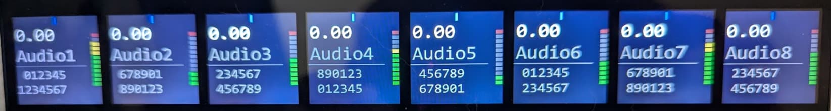
Notice I get the leading “1” on the first display, all the way left, and 7 characters. It then automatically skips the first space on each display after that, including the top line when it wraps around back to the first display.
But now if I write a single character at the 7th position and every 6th after that I can fill in the gaps at the beginning of each segment.
My sysex to get that display is:
F0 00 00 67 15 13 00 31 32 33 34 35 36 37 38 39 30 31 32 33 34 35 36 37 38 39 30 31 32 33 34 35 36 37 38 39 30 31 32 33 34 35 36 37 38 39 30 31 32 33 34 35 36 37 38 39 30 31 32 33 34 35 36 37 38 39 30 F7
F0 00 00 67 15 13 00 41 F7
F0 00 00 67 15 13 07 42 F7
F0 00 00 67 15 13 0d 43 F7
F0 00 00 67 15 13 13 44 F7
F0 00 00 67 15 13 19 45 F7
F0 00 00 67 15 13 1f 46 F7
F0 00 00 67 15 13 25 47 F7
So it is possible to use seven characters per line, but it seems like the kind of thing they might “correct” at some point.
Their firmware looks like it’s trying to do something clever to preserve compatibility with some old protocol, but it doesn’t seem like it’s working properly.
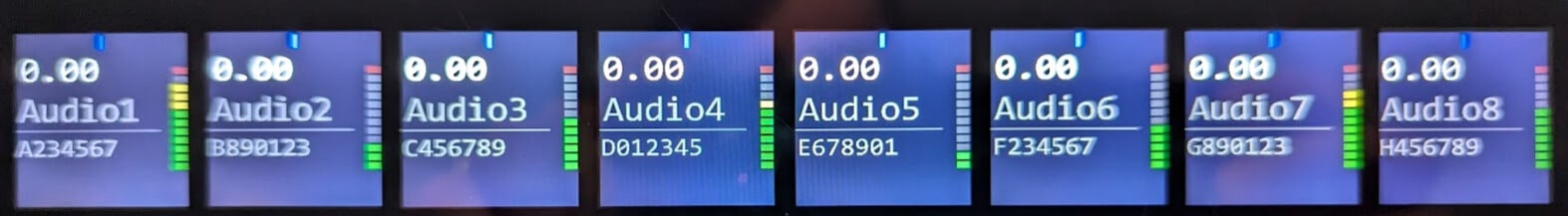
edit: Image below is from the Icon website… looks like the there are some alignment problems on there as well. Although those are at least consistently showing 7 characters per channel.

ah funny observation with the image from their website, the fact that it’s so ugly there as well. But yeah as you also conclude it seems like they just tried to tie it in to some standard, but it’s not doing it correctly.
Which firmware are you on? Mine is 1.07.
Are you able to write 56 characters from 0x00 or does it also skip the first one then?
I doubt that Icon would spend time on it, just based on what I heard and experienced, but if they could give us another “DAW” mode that would tell the onboard processor to format things more loosely, so we could use the entire space of the displays and not have these weird formatting issues, that would be awesome.
The firmware for the Nano is up to v. 1.21. And even with that, I think some firmware issues remain that go beyond just the weirdness of the displays. My Nano has been collecting dust since I bought it because the MCU emulation still seems either buggy or not intuitive enough for me to spend the time to figure out what it’s doing.
I think my display exhibits different “strangeness” than yours because we’re on different firmware, and both aren’t doing what they’re supposed to. They’re just doing it wrong in different ways.
Given your discovery of the P1 protocols on port 4 I actually went ahead and bought a P1-M, which I just unboxed about an hour ago. I’m not going to get a chance to mess with it all today most likely, but I’ll probably spent a fair bit of time this weekend.
I wrote an MCU extension for GigPerformer a couple years ago that I was using with my Platform-M+ (and my old Behringer MCU clone before that.) My next step now is to adapt that to take advantage of the P1’s softbutton grid. What I’ve concluded from your discoveries with the P1-M and my experience with the Nano is that because the P1 protocols are essentially the same, but “broken” in different ways, I’m not going to spend the effort to write code that accommodates two different broken protocols. Instead I’ll focus on the P1-M, get that working as best we can, and then see if Icon has an interest in fixing the “quirks”.
Regarding that 56 character question - on the Nano it’s 49 characters. 7 on the first screen, six on the next 7. So 7 + 6x7 = 49 characters. When writing from 0x00 anything past the 49th character is ignored, and it doesn’t care if I write 49 characters or 400 characters. When I write starting at addresses that aren’t 0x00 it’s clearly doing some incorrect math about where it puts things.
If I’m writing starting at 0x38 then it does require I put in at least 56 characters, but everything past the 49th character wraps from the bottom line up to the top line. So there’s actually no mechanism to write to the second line cleanly by itself. It’s always going to mess up the start of the first line. If I want to write the entire display in one go the proper character length for the string is 97 characters, which places 7 on the lower left line, then six in every other slot. So 15x6 + 7. If I really want to get all 7 characters placed in every text spot I can, but I’d have to write that 97 character string first. That would end up leaving a blank space at the start of every text object (other than the very first) and then I can fill in the 15 spaces it left blank with one sysex command at a time.
That’s clearly broken, and also seems different than how it’s broken on the P1-M. It’s so obviously broken that I do expect we can get them to correct it at some point, but I’m not going to hold my breath.
You guys are going to make me buy another midi controller aren’t you? ![]()
Sounds like I’ve been lucky with the P1-M and their firmware compared to the Nano.
Curious if you got the P1-M in the end and if worked out better?
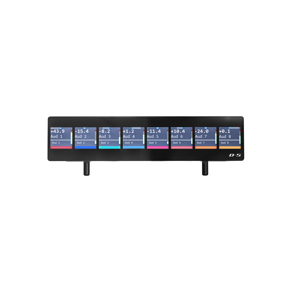
Haha, it is pretty awesome to have a 16 small customizable LCD buttons and that large display.
I did get the P1-M and it behaves much better than the P1-Nano.
I have gotten it to do what I want thus far. Now I just need to write the code to integrate controls for the display into a GP extension. I started, but with an end of summer vacation and kids starting school again I haven’t had a lot of time to code.
One thing I’m not thrilled with is there is a limited set of note events available to light the soft-buttons on the display. Basically just the note numbers that are not already used elsewhere on the device in standard MCU protocol. Nevertheless, it’s nice functionality to have.
Agree. Kinda strange. I think I could assemble a bit more available notes to cover 3 layers of buttons, but I’ll probably only use one layer anyway as I’ll overwrite them rather often with different functions.
Hey, guys! Thanks for this enlightening coversation. We sent this issue to one of the P1-M engineers, and this is his reply:
Thank you for the info.
The data format sent by scripts in different DAWs is different. At the beginning, only Bitwig supported this feature. The data format of Bitwig DrivenByMoss script includes parameters for 8 tracks and master track, which resulted in text misalignment. With the update of the script and firmware, this problem has been resolved.
Please ask users to use the latest firmware P1-M/X (firmware V1.08, released) and P1-Nano (firmware V1.22, not yet released).
In addition, the Bitwig/DP/Mixbus mode data format has undergone special processing (the data format sent by different scripts in different daws is different), while other modes use the standard data format (sending 56 bytes at once,refer to the following LCD protocol). If the script in DAW is sent to P1-M in the standard data format, there will be no text misalignment issue in modes other than Bitwig/DP/Mixbus.
Here is the complete LCD protocol.
1st LCD
Line1:0xf0 0x00 0x00 0x66 0x14 0x12 0x00 … … 0xf7
Line2:0xf0 0x00 0x00 0x66 0x14 0x12 0x38 … … 0xf7
The red part are the displayed characters, totaling 56 characters(7*8).
Fox example:
f0 00 00 66 14 12 00 41 75 67 69 6f 31 20 41 75 67 69 6f 32 20 41 75 67 69 6f 33 20 41 75 67 69 6f 34 20 41 75 67 69 6f 35 20 41 75 67 69 6f 36 20 41 75 67 69 6f 37 20 41 75 67 69 6f 38 20 f7
2nd LCD
Line1:0xf0 0x00 0x02 0x4e 0x15 0x13 0x00 … … 0xf7
Line2:0xf0 0x00 0x02 0x4e 0x15 0x13 0x38 … … 0xf7
The red part are the displayed characters, totaling 56 characters(7*8).
Fox example:
f0 00 02 4e 15 13 00 41 75 67 69 6f 31 20 41 75 67 69 6f 32 20 41 75 67 69 6f 33 20 41 75 67 69 6f 34 20 41 75 67 69 6f 35 20 41 75 67 69 6f 36 20 41 75 67 69 6f 37 20 41 75 67 69 6f 38 20 f7
Track color
0xf0 0x00 0x02 0x4e 0x16 0x14 … … 0xf7
The red part are the displayed RGB characters,totaling 24 characters(3*8).Each track contains 3 Bytes (R/G/B), ranging from 0x00-0x7f(high 7 bits).
Fox example:
f0 00 02 4e 16 14 7f 2b 02 6c 4e 07 00 00 00 00 00 00 00 00 00 00 00 00 00 00 00 00 00 00 f7
Please let us know how this works for you. Thanks!
This is great. Thanks for giving it some attention!
For simplicity, let me focus on two things that have been fixed (much thanks!) and two requests. Both requests should be pretty simple. One is clearly a bug fix, the other a minor enhancement that I think should be simple.
Fix 1 that’s working now:
The MCU protocol text display for the top two lines seems to work exactly to the MCU spec.
The MCU protocol allows you to write any number of characters at a time to the two lines on an MCU display. The displays are visually segmented as two lines, seven characters on each line, on 8 separate channel strips. That’s 7x8 characters per line, or 56 per line and 112 total.
Per the MCU protocol, how it always worked on the iCon M+, and how it now works on the P1-M, you can write the entire thing in one sysex string, or you can specify any arbitrary starting position and write however many sequential characters you want from there.
This seems to work perfectly now (from my limited testing), so thanks.
Fix 2 that’s working now:
For the bottom two rows of text (which don’t exist in the MCU protocol) we can successfully write to all 112 available characters (two lines of 8 strips of 7 characters). This is great, and a big improvement.
There are a couple issues with it still, however. In general the protocol really should work the same way as for the top two (MCU) text lines. It does not in a few ways, which I’ll describe next.
Related bug fix request
Two things that don’t work with those second two lines is are:
- writing to them all as one block of text (e.g., both lines in one sysex)
- writing to them starting from an arbitrary position.
first issue - With the MCU text protocol you can put all 112 characters in one sysex, starting from position zero, and it will write out to both lines. (This works for the top two lines on the P1-M, per MCU protocol.)
For the bottom two lines of text you can do it if you trick it into working by starting at position 0x38 (beginning of line 2). The first 56 characters will be “line two” and then the next 56 will wrap around and fill line one. However, if the sysex starts at position zero everything after the first 56 characters is ignored.
Second issue -
EDIT 3/16/25 - my original comments here applied when interacting with the MCU when “Bitwig” was selected as the DAW thru iMap. It turns out these issues can be avoided by setting “Live” or most of the others as the DAW thru iMap. We can also change what the P1-M thinks is the DAW through our own sysex, so the problem I described below (which I’m leaving in, hidden by a spoiler, for posterity) can be avoided. This was noted in the message above from @iCONProAudio but I didn’t not initially understand that.
Summary
The protocol seems to accept writing text starting at arbitrary positions (e.g., I can write a sysex of 7 characters starting at position 7) but it butchers the spacing and location when doing so.
I would think the algorithm for processing the sysex for the bottom two lines of text should be basically copy & paste from the code that’s now working perfectly for the top two lines above it (per the MCU spec).
Elaborating a little, just to make it clear…
There are now two different ways I could address the “third” line of text on channel strip two… Let’s say I want to write “0123456” to that position, right above knob 2. I could use
f0 00 02 4e 15 13 07 30 31 32 33 34 35 36 f7
or
f0 00 00 67 15 13 07 30 31 32 33 34 35 36 f7
both produce the identical result of
0 12345
on the display above fader 2.
Why this matters is that we may want to display the label for knob 2 (say “Rev Len”) above knob two, and the current value (say “1284 ms”) below it and update that value continuously as we turn the knob.
The MCU protocol was designed so we can do just that without touching anything other than the characters we are changing. The rest of the display will stay the same as we make changes just to the “1284 ms” part. This works fine on the top two lines (per the MCU spec) but not on the bottom two lines.
For the bottom two lines we have to rewrite an entire line to get them formatted correctly.
I can live with this, but it should work the same way as the MCU protocol. If there’s some “backward compatibility” issue you need to preserve you now have two different sysex headers to address those same two lines, and both are broken in the same way. If either one of those could be fixed to work the same as the top two lines (e.g., per MCU protocol) that would be great.
Summary: from a user standpoint, writing DAW or GigPerformer plugins to work with the P1-M, the routines for writing to the top two lines and bottom two lines of the display should be identical with the exception of the sysex header. For the top two we use “f0 00 00 66 14 12” and for the bottom two we have “f0 00 00 67 15 13” or “f0 00 02 4e 15 13”. The top two lines work perfectly, in accordance with MCU protocol. The bottom two do not (with either of those two headers). As a result we have to write substantially different routines to handle the bottom two lines because they’re not conforming to the MCU protocol properly (as the top two lines do).
Small feature request:
With the “soft buttons” on the 4x4 pad display, not all of them have the ability to be lit and unlit. I understand why this is. It corresponds to the original MCU protocol, where not all buttons could be lit. Because you want the device to look and respond like an MCU to DAWs this makes sense.
Those buttons (on the MCU and P1-M) work by sending note-on when touched. It’s up the DAW to light or un-light them, which (for light-up buttons) works by the DAW sending the same note-on (to light) or note-off (to unlight).
However…
You’ve given us the ability through iMap to assign whatever MIDI codes we want to each of those softbuttons. Mostly those are set up in iMap to mimic actual MCU buttons. But we have the ability to assign them MIDI events that lie outside the MCU protocol, and for those it would be very nice if they could be lit / unlit with note-on / note-off messages as well.
There is a note group (119-126) that is completely unaddressed by the MCU protocol. Anything we do with those will have no impact on any DAWs running pure MCU compatibility. So we should be free to use them as we want, which we currently can with the exception that they will not respond to the DAW sending light / unlight commands by note-on / note-off.
My request is simply to allow note-on / note-off events to on notes 119-126 to pass through to the part of the firmware that lights / un-lights those buttons. Very importantly, it should look at both note number and channel number. It’s important because with 16 channels of 8 notes we effectively have control of up to 256 buttons that are entirely outside the MCU protocol, thus do not break any MCU compatibility. With 256 potential soft-buttons outside the MCU protocol we could assign everything on all five pages of softbuttons to unique things.
One question -
What is the best way to provide additional feedback/questions?
Hey, @Vindes.
We just wanted to let you know we’ve submitted this information to the engineers, and we’re waiting on their reply.
Thank you very much.
iCON Pro Audio
Great, thank you very much!
An additional thought… I could simplify the last part of that request quite a bit I think. Nothing in the MCU protocol uses note-on/note-off events on anything other than midi channel 1. If the P1-M could simply light/unlight softbuttons using note-on/note-off messages on channels other than 1 it’s probably simpler, cleaner, and more logical than constraining that to the note numbers I mentioned.
e.g., if I set a softbutton in iMap to send note 0 messages on channel two, just let us light/unlight that with the same messages to channel 2. It seems the P1-M firmware just ignores note messages not on channel 1 even though iMap allows us to send them.