Hi, prices of midi pedals are a bit too much…So I made my own footswitch controller with exp pedal from korg nanokontrol.
Problem is:
When i’m NOT using the pedal (pot from nanokontrol) it sends CCs all the time. Ranging to 3 adjacent ones.
So if its at value 27. I get 25,26,29,28 one by one at random.
Is there a solution to only accept midi messages from this CC (22 channel 5) if it go above value 3± of the value that GigPerformer is getting?
It is annoying, cause if I change the rackspace, it move my default value even when I’m not using the pedal.
Oh if anyone is interested. I made my controller very DIY way I made a wooden case full of footswitches and one TRS socket then wired them to old printer connection (LPT). On the korg side I wired all the buttons, and one pot to the second LPT. And then just connect those to together. Oh and a pedal is 3d printed with a normal potentiometer wired to TRS. Unfortunately the long cable give some ±3 value play in the expression pedal. Nothing to worry about with buttons, but with exp there is a problem.
I am not sure if blocking unwanted midi cc via midi filter is a solution. You can try by adding a midi filter on the diagram screen and connecting omni to the filter and then blocking the desired ccs
This will be jitter coming from the potentiometer. I have experienced this with Arduino based hardware designs I have worked on. You would benefit from adding some smoothing circuitry to the pot - adapting something like the 2nd answer in this forum post:
It is basically adding a low-pass filter to the signal coming from the pot sweeper to filter out the jitter. I ended up also adding smoothing algorithms to the code to get a completely stable value.
var v_last_value : integer = 0
    v_current_value : integer

On ControlChangeEvent(m : ControlChangeMessage) Matching 11
 v_current_value = GetCCValue(m)
 if v_current_value >= v_last_value +3 or
    v_current_value <= v_last_value -3 then
  SendNow(m)
  v_last_value = v_current_value
 end
End
@DaveBoulden Yes I thought about arduino when writing about it. I think I must try that too! Thanks!
@pianopaul You are a master, I was looking for a solution earlier, and saw your scripts, they are great!
This works too! Couldn’t get to work on my rig, but made new. On my I saw only values in global midi monitor, but testing on new empty rig works fine on rackspace midi monitor.
Could you or someone explain how to add this to expression widget? Straight to plugin is simple, but I should use widget from what i know.
BTW is it possible to only use this script if I’m not using the pedal? So as soon I’m moving it it omits the ±3 rule? And get back to it after not using again?
You could use the scriptlet in the global rackspace
and then in the script code inject the messsage into the Local GP port and then learn the widget from the Local gp port.
var v_last_value : integer = 0
    v_current_value : integer

On ControlChangeEvent(m : ControlChangeMessage) Matching 11
 v_current_value = GetCCValue(m)
 if v_current_value >= v_last_value +3 or
    v_current_value <= v_last_value -3 then
  InjectMidiEvent("Local GP Port", m)
  v_last_value = v_current_value
 end
End
if Abs(v_current_value - v_last_value) >= 3
  then ....
Also, I’m not really a fan of using software to fix a hardware problem — today, your controller is skipping +/- 3 … what happens when tomorrow it starts skipping +/- 4 ?
If you’re not touching that controller, it shouldn’t be sending out anything. It seems to me that the real fix is that proposed by @DaveBoulden
To be fair, when I built my most recent project that was scanning potentiometers, I had to use a combination of hardware filtering and software to arrive at stable resistance readings. There is so much variation in the quality of converters embedded in microcontrollers that can also be effected by the quality of the power supply and the quality and age of the potentiometer itself can cause more issues. I ported my project from Arduino to Teensy to improve the stability of the converters.
If you are feeding the converters on a commercial unit where you can’t change the microprocessor, as is the case here, then anything the hardware modifications (i.e. the resistor/capacitor filter) doesn’t completely solve (i.e. the jitter) will need to be mopped up by the software. However, it is best to solve as much via the circuit design as possible as any smoothing applied to the values being read from the converter is going to introduce lag to the responsiveness of controller changes.
The solution offered here, whilst it will solve the jitter, will also reduce the resolution of the controller data as it has to change by more than 3 (or whatever threshold) before the next changed value is acted upon. A proper smoothing algorithm will detect trends and evaluate change-acceleration to more accurately smooth out the readings whilst still retaining decent resolution of the data itself.
Guys, Im very glad that you found some time to help. I will firstly check the software solution, but definitely go with hardware one. If hardware wont be enough I will use it combined. Will update with more info after modifications and testing
When using an Arduino and alike for A/D conversion you should average the samples coming from the pedal. The trick with the capacitor helps, but not when the pot is right between two values. I average it this way:
volatile byte adc1 = 0;

void loop
{
    float EMA_a = 0.3;       // initialization of EMA alpha
    int EMA_S1 = 0;          // initialization of EMA S

    while(1)
    {
        adc1 = (byte)(analogRead(A2));
        EMA_S1 = (EMA_a * adc1) + ((1 - EMA_a) * EMA_S1);
        adc1 = EMA_S1;

        // Do something good with the adc1 value...
    }
}
EMA_a is the percentage that determines how strong the new adc value influences the averaged one. In this case the ‘mix’ is 30% new value + 70% the averaged value (stored in EMA_S1).
Keep in mind that floating point support is not available on all Arduino’s. It will then do FP in software, which is much slower, but with 1 adc you should be able to do this 500 to 600 times per second. At least the Adafruit Trinket could do that (48MHz).
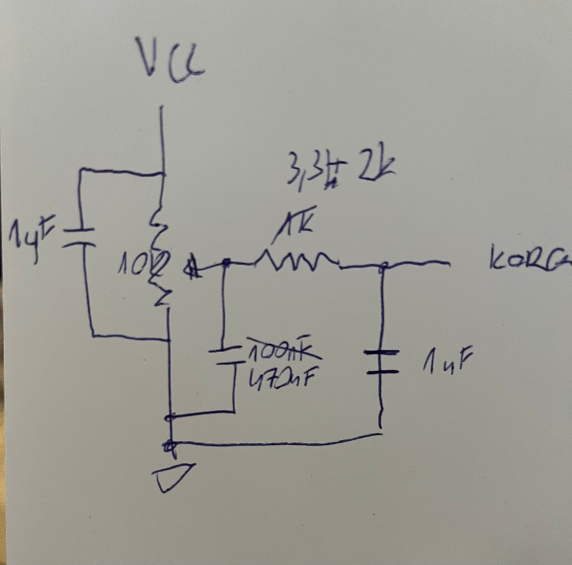
Guys thank you for your input. Modified solution from @DaveBoulden made the trick. I contacted electrician friend, and he suggested a bit more developed solution. Here is a crude schematics I made. I used two resistors, because I didn’t have suggested 4.7k. Stared with smaller values, and tested if it would do the trick. Finally ended with 1uF, 3,3k+2k, 470nF and 1uF for 10k resistor. Maybe someone will look for solution. So here it is
If this device is usb powered then do not place too many capacitors parallel to the power. Some usb ports switch off, some start smoking, others don’t care and are happy. The 0.47 uF also counts when the pot is turned to max.